


OVERVIEW
If you looked at our last tutorial, you saw that we were using two different code / sketch…
One for the Transmitter and a different one for the Receiver.
Although there is no problem doing it that way, sometime you could get mixed up and upload the wrong one to the wrong board.
In this tutorial we will see an easy way to use one sketch that combines both and upload it to both boards, and let the code detect which board it’s running on and do different actions based on that detection.
PARTS USED
Arduino UNO
Arduino NANO
Arduino NRF24L01
These are Amazon affiliate links...
They don't cost you anything and it helps me keep the lights on
if you buy something on Amazon. Thank you!
TRANSMITTER CONNECTIONS
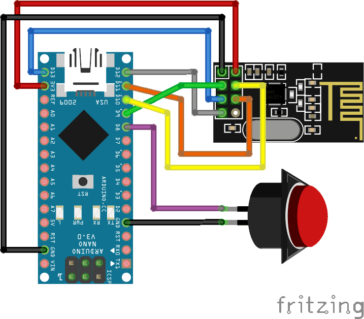
The transmitter which uses a NANO is using the same connections used in the prior tutorial:
Here are the connections:
The Switch is connected to the GND and Pin 8 on the NANO
The NRF24L01 pins:
MISO connects to pin 12 of the NANO
MOSI connects to pin 11 of the NANO
SCK connects to pin 13 of the NANO
CE connects to pin 9 of the NANO
CSN connects to pin 10 of the NANO
GND and VCC of the NRF24L01 are connected to GND and 3.3V of the NANO
The NRF24L01 uses the SPI communication protocol, so you need to make sure that you are using the SPI pins of the version of the Arduino board you will want to use.
The NANO and UNO boards have the same ones:
Pin 11 = MOSI (Master Out Slave In)
Pin 12 = MISO (Master In Slave Out)
Pin 13 = SCK (Serial Clock)
But if you plan to use let’s say a MEGA 2560 then those pins will be different.
Pin 51 = MOSI (Master Out Slave In)
Pin 50 = MISO (Master In Slave Out)
Pin 52 = SCK (Serial Clock)
RECEIVER CONNECTIONS

The Receiver schematic is the same except that we added a jumper from the A0 pin to GND.
This will be used by the sketch to detect if it’s running on the Receiver or the Transmitter.
Here are the connections:
The WS2812 RGB Stick DI (digital In) pin is connected to Pin 8 on the UNO
GND and VCC are connected to the GND and 5V of the UNO
The A0 pin of the UNO is connected to GND
The NRF24L01 pins:
MISO connects to pin 12 of the UNO
MOSI connects to pin 11 of the UNO
SCK connects to pin 13 of the UNO
CE connects to pin 9 of the UNO
CSN connects to pin 10 of the UNO
GND and VCC of the NRF24L01 are connected to GND and 3.3V of the UNO
THE "ONE" CODE
In this tutorial we will be using only one piece of code (sketch) that will be uploaded to both the Transmitter (NANO) and the Receiver (UNO).
The code will read the state of the A0 pin and detect if it’s HIGH or LOW.
We set the A0 pin to HIGH at start, since there is nothing connected to the A0 pin of the NANO, it will stay HIGH.
But since we connected the A0 pin of the UNO to GND, then it will be LOW even if we set it to HIGH at startup.
If it’s HIGH then it means it’s running on the NANO (Transmitter) and if LOW then it’s the UNO (Receiver).
After that it’s just a matter of doing actions in the code based on the A0 pin state.
As always, Don’t forget to watch our Tutorial video for more information.
/* Start of Code */

/* Arduino One Code/Sketch for Two Functions

Created by Yvan / https://Brainy-Bits.com
This code is in the public domain...
You can: copy it, use it, modify it, share it or just plain ignore it!
Thx!

*/

// Include needed Libraries at beginning
#include "nRF24L01.h" // NRF24L01 library created by TMRh20 https://github.com/TMRh20/RF24
#include "RF24.h"
#include "SPI.h"
#include "FastLED.h" // FastLED library for WS2812 RGB Stick http://fastled.io/

// Define the Pins used
#define NUM_LEDS 8 // Number of leds on stick for Receiver
#define LED_PIN 8 // Digital In (DI) of RGB Stick connected to pin 8 of the UNO (Receiver)
#define SwitchPin 8 // Arcade switch is connected to Pin 8 on NANO (Transmitter)
#define board_select A0 // Pin used to detect the running board

// Used Variables
int SentMessage[1] = {000}; // Used to store value before being sent through the NRF24L01 (Transmitter)
int ReceivedMessage[1] = {000}; // Used to store value received by the NRF24L01 (Receiver)
int running_board; // Used to store the identify of the running board
const uint64_t pipe = 0xE6E6E6E6E6E6; // Needs to be the same for communicating between 2 NRF24L01

// Init components
RF24 radio(9,10); // NRF24L01 uses SPI pins + Pin 9 and 10 on UNO and NANO
CRGB leds[NUM_LEDS]; // FastLED Library Init (Receiver)


void setup()
{

// Make board_select Pin HIGH on start
pinMode(board_select, INPUT);
digitalWrite(board_select,HIGH);
delay(100); // Little delay to make sure it is stable at HIGH

// Check to see which board is running
if ( digitalRead(board_select) ) { // If HIGH then it's the NANO (transmitter)
running_board = 0;

pinMode(SwitchPin, INPUT_PULLUP); // Make the switch pin input with pullup resistor
digitalWrite(SwitchPin, HIGH); // Make switch pin HIGH at start
}

else { // Then the pin was detected LOW meaning it's the UNO (Receiver)
running_board = 1;

pinMode(LED_PIN, OUTPUT); // Set RGB Stick UNO (receiver) pin to an OUTPUT

FastLED.addLeds<NEOPIXEL,LED_PIN>(leds, NUM_LEDS); // Setup FastLED Library
FastLED.clear(); // Clear the RGB Stick LEDs

for(int x = 0; x != NUM_LEDS; x++) { // Light up LED Stick all Red at startup
leds[x] = CRGB::Red;
}

FastLED.setBrightness(50);
FastLED.show();
}

radio.begin(); // Start RF24L01 on both boards

if ( running_board == 0 ) // 0 = Nano (transmitter)
{
radio.openWritingPipe(pipe); // Open writing pipe for transmit
}
else // if not = 0 then it's the UNO (Receiver)
{
radio.openReadingPipe(1,pipe); // Open reading pipe for receive
radio.startListening();
}

}

void loop() {

if ( running_board == 0 ) { // Then it's the Transmitter

if (digitalRead(SwitchPin) == LOW){ // If Switch is Activated
SentMessage[0] = 111;
radio.write(SentMessage, 1); // Send value through NRF24L01
}

else {
SentMessage[0] = 000;
radio.write(SentMessage, 1);
}
}

if ( running_board == 1 ) // Then it's the Receiver
{
while (radio.available())
{
radio.read(ReceivedMessage, 1); // Read information from the NRF24L01

if (ReceivedMessage[0] == 111) // Indicates switch is pressed
{
for(int x = 0; x != NUM_LEDS; x++)
{
leds[x] = CRGB::Green;
FastLED.show();
}
}
else
{
for(int x = 0; x != NUM_LEDS; x++)
{
leds[x] = CRGB::Red;
FastLED.show();
}
}
delay(10);
}
}
}

/* End of Code */
TUTORIAL VIDEO
DOWNLOAD
Copy the above Sketch code in your Arduino IDE software to program your Arduino.
Used Libraries:
Download The NRF24L01 Library created by TMRh20 here:
Download The FastLED Library created by focalintent here: https://github.com/FastLED/FastLED/releases
Once downloaded, just extract the content of the zip files inside your “arduino/libraries” folder.
Comments